This site uses cookies to provide an optimized shopping experience. By using this site, you agree the use of cookies within our privacy policy.


Featured Depot Deal
Top Categories
-
 Test and Measurement Equipment
 -
 HVAC-R Tools and Supplies
 -
 Broadcast and Video
 -
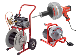 Drain Maintenance
 -
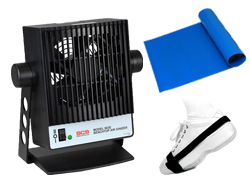 Static-ESD Control
 -
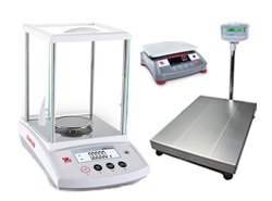 Scales and Balances
 -
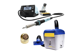 Soldering and Desoldering
 -
 Datacom and Network Test
 -
 Hand and Power Tools
 -
 Inspection Tools, Lights, Magnifiers, and Microscopes
 -
 Instrumentation and Lab Equipment
 -
 Wire and Cable Management


Top Brands

Featured Products
-
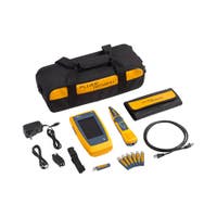 Fluke Networks LIQ-KIT LinkIQ™ Advanced Cable + Network Tester Kit$2,761.95 Price $3,346.99
 -
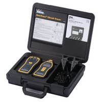 IDEAL Electrical 61-957 SureTrace 957 Circuit Tracer Open/Closed$1,179.01 Price $1,310.01
 -
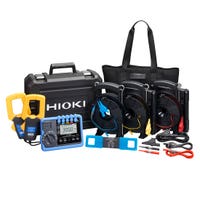 Hioki FT6041-91 Earth Tester Kit with Clamp Sensors and Accessories$3,024.00 Price $3,150.00
 -
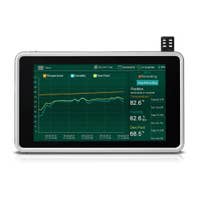 Extech RH550 Humidity/Temperature Chart Recorder with Touch-Screen$457.29 Price $519.00
 -
 OHAUS ISHD16HDG US Incubating Heavy Duty Orbital Shaker, Orbital, 0.75 in./19 mm, 15-500 rpm, 120 V, US$3,849.95 Price $4,430.00
 -
 Fluke SMFT-1000/PRO Multifunction PV Tester and Performance Analyzer with Trutest PVLEAD3$5,388.95 Price $5,999.99
 -
 Klein Tools ET450 Advanced Circuit Tracer Kit$249.99 Price $374.98
 -
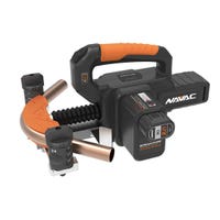 NAVAC NTB7L BreakFree Power Tube Bender Kit, 7/8 in Max OD, 7.2V 2Ah 14.4Wh$488.00 Price $679.00
More Ways to Save

Free Shipping Over $75*
Shipping is free when you spend $75 or more. Some exclusions apply, learn more.

Education Pricing & Discount Programs
Special savings from leading brands are available for educational institutions.

Instant Savings on Refurbished Equipment
Receive big discounts on top products when you shop our used and refurbished equipment.